Implemented Features
What’s up in the hydraulics department? You may not have noticed, but lately some items have made their way into the development version.
Bleed System Interaction
Now that we have the first iteration of our custom bleed system in, the hydraulics system has been modified so that it interacts with air pressure. In fact, each hydraulic reservoir is air pressurised, allowing the pumps to work efficiently. The bleed system will provide this air pressure and a bleed system failure will trigger a pump low air pressure fault, causing the pumps to lose their efficiency and pump less.
If it occurs at cruising altitude, you will lose a lot of hydraulic power. Get the plane to a lower altitude and you will see the hydraulics slowly coming back to life. This is already implemented and you can play with these scenarios using the new hydraulic failures available in the EFB menu.
Emergency Generator
The blue circuit emergency generator is now simulated and will spin at a valve-regulated 12000 rpm to provide electrical power from hydraulic flow. The RAT will provide that flow in the event of an electrical failure and will get you safely on the ground. While there is no 3D RAT model - this will come with the remodel - it has been simulated, with only small features missing (e.g. the anti-stall system,which will come later).
Physics Based PTU
Until recently, we only had a simple PTU flow model, but a proper power transfer unit implementation is far more complicated than a line of code that tells it to activate at a pressure difference of 500psi. In fact, it does not always bark - it can also provide hydraulic power continuously.
To model this properly, we switched the PTU to a physics-based simulation, which will react to pressure variations and make the PTU mechanical shaft spin in a realistic manner. Should the green or yellow system leak or otherwise lose hydraulic fluid, PTU will spin faster, and when we model the temperature, you will quickly get into trouble! All of this will soon be used by the sound engine so the continuous operation of the PTU and its recognizable slow growling sound can really shine.
Flaps and Slats
We recently connected flaps and slats to the hydraulics system, which is a surprisingly complicated system. While we are working hard on modelling the system in its entirety, we have introduced a medium-fidelity implementation that will make hydraulic interactions more realistic.
Flaps and slats are moved by four hydraulic motors connected through differential gearboxes, all of which are now connected to their corresponding hydraulic lines. Flap and slat deployment times will now depend on your hydraulic configuration, as they use a lot of hydraulic flow to move. Dual engine operation will give you nominal extension times, but if you try to use only the yellow electric pump to deploy both slats and flaps, be prepared to wait a good amount of time for them to fully extend.
Aileron Control
Why are the flight controls moving in a cold and dark state?
Don’t panic, it’s just the default MSFS flight controls!
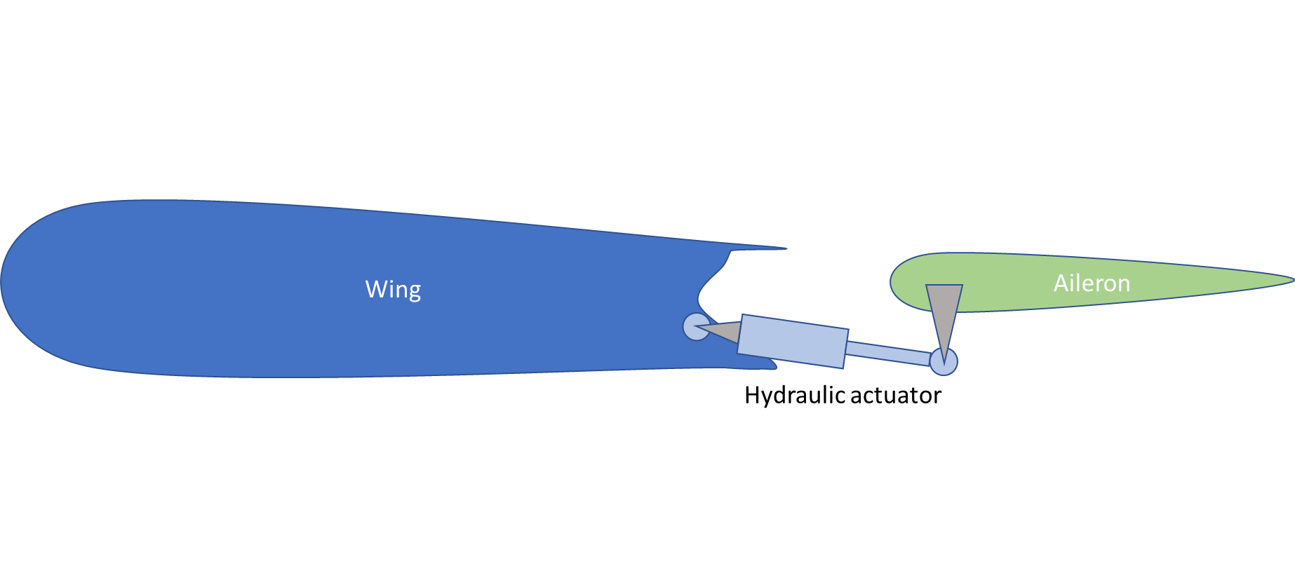
In one of our previous NOTAMs, we talked about cargo door operation using a full physics-based simulation of the hydraulic actuators. This will eventually be expanded to all actuators in the aircraft, so you can expect fully realistic flight controls in due course. As a reminder, the A320 is basically controlled by flight computers that send commands to hydraulic actuators. This will be fully simulated in the A32NX, where each actuator will receive orders and move their corresponding control surface to the commanded position. Since we do enjoy having some fun, we are now able to simulate full hydraulic servo position control loops in real-time.
Ailerons are the first control surfaces to get this. Each aileron is controlled hydraulically by servo actuators trying to reach a commanded position, as shown below:
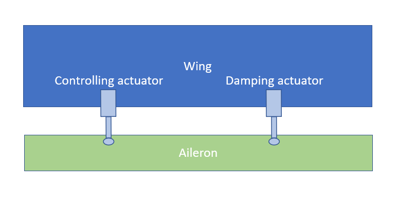
There are two actuators controlling each aileron. One is the master actuator, controlling the position, and the other one is a slave actuator used in damping mode. These control modes are simulated for all four actuators and will be activated accordingly as commanded by the flight computers. The slave/master configuration can be switched according to the state of the flight computers.
Note that this is the first step towards implementing low-level hydraulics. Right now, the associated flight computer logic is a mere placeholder and the hydraulics implementation only affects visuals (not flight physics). Aerodynamic forces are also not computed yet, so do not be surprised if you see a drooping aileron in flight - more on this in the next section.
Again, do not panic. Maybe a showcase of the moving surfaces will do the trick.
In the video above, you can see the famous aileron droop and aileron position control when the hydraulic servos are active. This showcase clip also demonstrates how the yellow electric pump is fully simulated, as you can hear its pitch changing dynamically. What can also be seen is the PTU acting in a continuous manner, save for the point where it reaches the 500psi pressure difference - this is where it acts on its yellow side displacement control, barks loudly and greatly impacts the electric pump pitch. We plan to improve the hydraulics soundscape soon.
Now a more realistic case: if your plane finds itself upside down while on the ground, obviously the aileron droop will go up! Uh wait… Down… Well you get my point!
Coming Soon to Hydraulics
As we progress, we will simulate all control surfaces in the same realistic manner. The experimental version already has an early implementation of elevator and rudder hydraulic simulation, including a realistic left/right elevator split. Do not hesitate to give it a try and watch them droop or come to life depending on the hydraulic state of the plane.
Even in this early version, we are already simulating the fact that in certain speed/pitch demand conditions, the elevator is commanded by all actuators instead of the ‘one slave/one master’ actuator combination. This means that the elevator gets the maximum available power to fight against massive aerodynamic forces. Sadly, as we mentioned earlier, the surfaces are not affected by any aerodynamic forces due to MSFS SDK limitations, so that control surfaces will even droop in flight if hydraulic power is lost.
Well, fret not as this will soon be sorted out - we will compute our own aerodynamic model for the aforementioned control surfaces, so that they will actually react to external forces as they would in real life. While you will not notice it during normal ops, it will shine when the hydraulics fail, and stop providing enough power for the surfaces to respond correctly. This way, the hydraulics will naturally impact flight characteristics as they would in real life. Here is an early demo of what to expect with the new aerodynamic system. Yes, if there is enough wind, the elevator or ailerons can droop UP!
General Information
Stay up to date with information from FlyByWire Simulations by following our social media!
If you require support or would like to submit a bug report please see the links below:
When submitting an issue or asking for support to do the following:
- Visit our Reported Issues Documentation for common problems and workarounds.
- Ensure that your issue has not already been reported on our GitHub.
Download the latest version of the A32NX & A380X:
Safe skies and happy flying!
Editors: Kevin, Valastiri