Overview
Welcome back to another February NOTAM! This week we are covering updates to a few of our systems in the A32NX.
- Fly-By-Wire
- Autopilot
- Autothrust
- Flight Warning System
- Air Conditioning
In case you missed last week's NOTAM you can check it out here.
FBW / AP / ATHR Improvements
We have performed various fly-by-wire (FBW), autopilot (AP) and autothrust (ATHR) tests in a full flight simulator. We used the findings to make adjustments to the AP, FBW and ATHR, which have also been verified and approved by real A320 pilots.
Fly-By-Wire System
On the FBW front, we have made some adjustments to the pitch law and can confirm that the existing roll and yaw laws are already realistic, i.e., they match what we experienced in the full flight simulator. We have increased the attainable pitch rate at lower speeds. As a result, the pitch law is now more sensitive in these scenarios. Additionally, we have adapted the pitch law to better compensate for speed changes and speedbrake deployment.
In line with these changes, we have updated our joystick setting recommendations. The recommended sensitivity for the pitch axis is now +/- 30%, which better mimics the increased force needed to hold the real sidestick full back or forward (note that the real Airbus sidestick has a 2-step force curve). In addition, you need to pull the sidestick about ⅓ of the way back when the flare mode is active during landing (see the video below).
Autopilot
Furthermore, we have also improved some of the laws and mode initiation mechanisms of the autopilot systems. First, we have made several changes to the arming (ALT) and engaging mechanisms of ALT and ALT* modes. We have also reworked the conditions of arming ALT and engaging ALT. In addition, ALT* is now inhibited 3 seconds after changing the FCU altitude, and the plane now overshoots the target altitude in a realistic way.
Second, the target load factors that are used to guide the autopilot are now separated for every law and situation. As an example, the V/S mode usually targets a load factor of 0.05G, but during the level off phase (i.e., when you push the V/S knob on the FCU) it now aims for 0.1G.
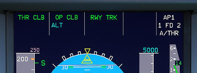
We previously showcased the improved Speed/Mach law in September. Since then, the Speed/Mach law has been extended with further edge cases. We have adjusted the minimum vertical speed limitations under the Open Descend (OP DES) or Open Climb (OP CLB) modes. For example, if ATHR is off and the pilot manually pushes the thrust levers to full thrust, the aircraft will continue to descend at a minimal rate while still accelerating.
This is not to mention other changes we have made. We discovered that the SRS and RWY modes do not automatically disengage when pulling the thrust levers to idle during a rejected takeoff (RTO). To disengage them, you need to turn off and on both flight directors again. Not only that, the HDG / TRK law has been improved in terms of bank angle limit for changes up to 10° in course.
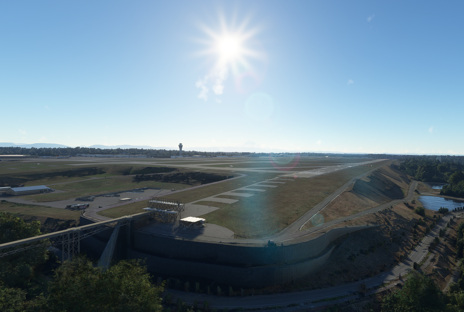
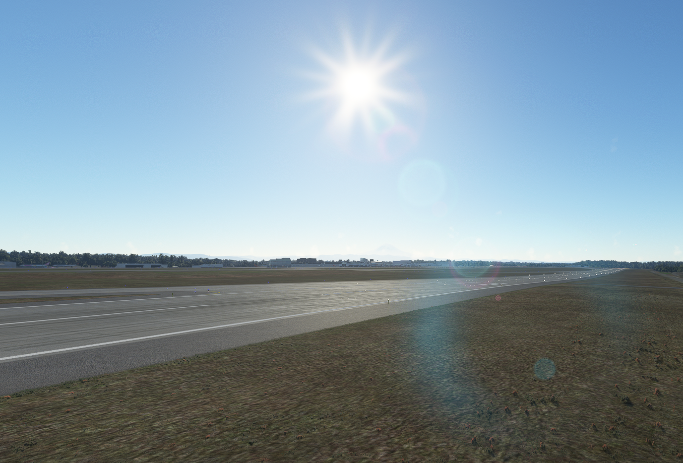
Finally, we have tuned and improved the LOC, FLARE and ROLL OUT Autoland laws. A new filter has been designed and implemented for the FLARE law to improve measurement of vertical speed relative to the ground using the radio altimeter. Such a filter is needed to ensure normal behaviour on sloped runways. Due to this, the A32NX can now perform approaches on runways with pre-threshold terrain profiles that can induce abnormal landing system behaviour. A special operational test and evaluation program is required before approving any CAT III operations for real aircraft on these types of runways. One very prominent example is Seattle-Tacoma/KSEA’s 16R.
Background on FLARE law
In the following section, we would like to provide some insights into the flare law.
The flare law has the task of reducing the plane’s vertical speed from approach to touchdown. This needs to work at different weights, centres of gravity, wind speeds and directions, as well as runway slopes. We will briefly discuss how it handles sloped runways.
The two figures below show the radar altimeter signal during an Autoland approach for EDDM 26L and KSEA 16R. The signal for EDDM 26L is stable and smooth. In contrast, the KSEA 16R shows a typical noise of a radio altimeter signal, as highlighted by the orange box. Remember that every object on the ground, like trees or houses, is picked up by the RA. We can also see the wall (red arrow) just before the threshold of runway 16R.
 EDDM 26L
 KSEA 16R Radio altimeter
 KSEA 16R Terrain profile around runway threshold
 KSEA 16R Runway slope
As mentioned above, one of the challenges we faced is accounting for the slope of the runway. Due to this potential slope, the flare law cannot just bring the absolute vertical speed to the target value. It is also important to bring the vertical speed relative to the ground closer to the target landing rate. The only way to do this reliably is to use a radio altimeter. This is also the reason why this device is so essential for an Autoland.
The signal from the radio altimeter reflects height - not speed - so the signal needs to be derived. Derivation of a noise signal is a challenge. Thus, the radio altimeter signal filter has to strike a careful balance between reactivity and smoothness; a wall just before the threshold of the runway presents a challenge for filter parameter adjustment.
With this in mind, we devised the following filter for radio altitude signals:

The following figure shows the Autoland at EDDM, runway 26L. The blue line shows the vertical speed relative to the air, and the orange line shows the vertical speed relative to the ground (based on the filtered radio altimeter signal). It can be seen that both lines are very close together because EDDM 26L has a clean terrain profile in front of the runway and the runway has no slope:

In contrast, the following two figures for KSEA 16R and KLAS 01L show a discrepancy between vertical speed relative to the air and ground. The runway slope can also be seen because there is a difference between the two lines even after the touchdown.
 KSEA 16R
 KLAS 01L
The flare law uses the vertical speed of the aircraft relative to the ground as an input for a vertical speed tracker to adjust the landing rate to an appropriate level for touchdown.
Autothrust
In relation to the autopilot system, we have improved the thrust transitions in case of CLB, DES, OP CLB, OP DES. We have also improved the SPEED / MACH law of the Autothrust system so that engines react more quickly to better ensure speed is kept in a range of -5 to + 10 knots of target approach speed (Vapp).
We have also improved the thrust limits. This applies to both the thrust limits themselves and interaction with the CLB limit during flex temp takeoffs. Furthermore, we have improved the N1 base loop controller to better achieve the N1 target, although this does not work in all cases yet. For this reason, the engine model and thrust limits will get further accuracy improvements, which are already in progress.
We also discovered that ATHR arming is related to SRS engagement. When SRS does not engage on takeoff, the ATHR will not arm. Keep this in mind when you take off without having set a V2 speed.
Last but not least, we have adjusted the gains of the ATHR Speed/Mach law to achieve better speed control performance during acceleration or deceleration, such that the time to reach the commanded speed is now lower. You can see one example in the following video.
New Flight Warning System
While work on our aircraft systems has progressed at an incredible pace, our as-of-yet rudimentary ECAM has not seen a lot of changes since the early days of FlyByWire. We can only showcase the depth of our new electrical and hydraulic systems when failures and knock-on effects cause accurate aural warnings and ECAM actions to appear. For this, we need a properly-modelled Flight Warning System (FWS).
Over the past months, we have been developing an in-depth simulation of the Flight Warning Computers (FWCs) from the ground up. These devices are crucial components of the FWS on the real aircraft and are capable of redundantly monitoring thousands of signals across most aircraft systems to help pilots prioritise and respond to failures. While there is a lot of groundwork to be built before we can hook up the systems we already have today, a large portion of this groundwork has already been completed. We are in the process of completing the first iteration of the system, which is capable of monitoring the most critical systems, as well as emitting voice callouts and some other special sounds.
This first version will include a reworked altitude alert (also known as the ‘C-chord’), the altitude callouts (e.g.“Five Hundred”) being triggered at more accurate heights, and a little-known feature called ‘intermediate callouts’ where the FWCs call out the precise height over ground when too much time has passed since the last call (e.g. “One Hundred and Twenty”). It will also feature the “Stall” callout together with the infamous ‘cricket’ noise, although you might find it very hard to trigger in the normal law. However, just like in reality, the FWCs will keep a watchful eye on the plane; if you ever manage to trick our FBW protections and end up with an unusual angle of attack, you will get the appropriate warning.
While those features may sound simple, we have modelled them to an extreme level of accuracy, reproducing exact logic found on the real aircraft. This is backed by hundreds of hours of research, countless tests in the real aircraft and detailed study of undocumented behaviours. The first version of the FWC will provide a solid framework for the following versions; after this update, we will turn our attention to the status page and the textual ECAM warnings themselves.
Air Conditioning
We have introduced the first building blocks of the air conditioning system. The cabin will now be able to warm and cool in accordance with outside conditions and the number of passengers on board. The heat transferred through the walls has been modelled in detail, as well as the effect of opening or closing doors. The air flow delivery system has also been overhauled and modelled as per the real aircraft.
Try it out and observe the different conditions that make the flow of air into the cabin get higher or lower. Play with the overhead knob and notice how increasing or decreasing the flow has an effect on the cabin temperature and the rate of change. From now on, you better remember to turn on the APU when sitting at the apron on a hot summer afternoon in, say, Dubai, if you do not want your passengers to melt!
General Information
Stay up to date with information from FlyByWire Simulations by following our social media!
If you require support or would like to submit a bug report please see the links below:
When submitting an issue or asking for support to do the following:
- Visit our Reported Issues Documentation for common problems and workarounds.
- Ensure that your issue has not already been reported on our GitHub.
Download the latest version of the A32NX & A380X:
Safe skies and happy flying!
Editors: Kevin, Valastiri